Part 1: Walking at Home as Virtual Sightseeing — Concept and Step Detection

The Problem: Stuck at Home, Starved for Movement
In 2020, the COVID-19 pandemic confined billions of people to their homes. Beyond the obvious health concerns, two quieter forms of stress crept into daily life: chronic lack of exercise and the inability to go anywhere. Walking, traveling, sightseeing — the simple pleasures of moving through the world — were suddenly off-limits.
Many people found themselves dealing with fatigue, restlessness, and a sense of monotony. Gyms were closed. Parks were crowded or restricted. And the beautiful places you dreamed of visiting might as well have been on another planet.
I wanted to address both problems at once. The result was a concept I called Virtual Sightseeing by Walking at Home — an Android application that turns the simple act of stepping in place into a virtual tour through real-world streets and scenic spots, projected onto your living room TV.
The Concept: Walking in Place Meets Street View
The idea is straightforward:
- Walk in place while holding your smartphone (or keeping it in your pocket)
- The smartphone detects your walking motion using its built-in sensors
- Each detected step advances a Google Street View panorama displayed on your TV via Chromecast
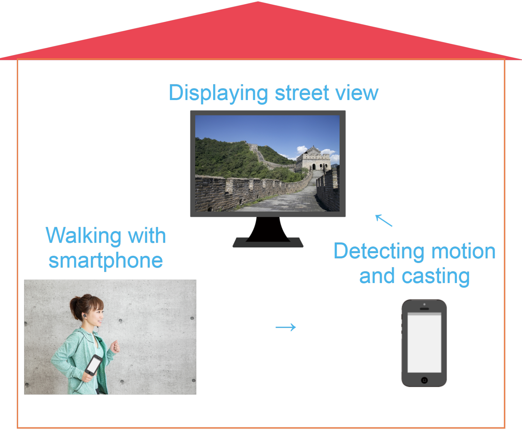
The experience feels remarkably natural. You walk in your living room, and the TV shows you strolling through the streets of Paris, hiking trails near Mt. Fuji, or exploring neighborhoods in Sydney. The physical movement is real exercise — raising your thighs, swinging your arms — and the visual feedback creates a sense of actually traveling.
To cast the smartphone screen to the TV, we use Google Chromecast paired with the Google Home app. This keeps the setup simple and affordable — no specialized hardware beyond a smartphone and a Chromecast dongle.
Why Walking in Place Actually Works as Exercise
Before dismissing stepping in place as trivial, it is worth noting that exercise physiologists consider it a legitimate form of aerobic activity. Professor Kenichi Nemoto of Matsumoto University’s Graduate School recommends a specific technique: raise your thighs slowly and high, and swing your arms with your fingers extended, pulling them far back. After just five minutes of this deliberate stepping, you can feel perspiration building and your metabolism increasing.
The key insight for this project is that this style of walking produces distinctive, measurable motion patterns — patterns that a smartphone’s accelerometer can reliably detect.
Two Sensor Challenges
Building this application required solving two distinct motion-detection problems:
- Detecting forward walking (stepping in place) — handled by the accelerometer
- Detecting turning (looking left, right, or around) — handled by the gyroscope
This first article focuses entirely on the accelerometer-based step detection. Part 2 will cover the gyroscope, the Street View integration, and the complete demo.
Prerequisites
The development environment for this project:
- Android Studio 3.6.3
- Android 9.0 (API Level 28)
- Latest Android Build Tools
- Google Play Services
The pedometer implementation references Google’s open-source simple-pedometer project, while the Street View integration references googlemaps/android-samples.
Implementing the Pedometer
The core challenge of step detection is distinguishing genuine walking motion from random vibrations, phone adjustments, or other incidental movements. A smartphone sitting on a desk might pick up vibrations from a passing truck. Someone fidgeting with their phone produces acceleration data. The pedometer must filter all of this out and respond only to the rhythmic, multi-axis motion pattern that characterizes walking.
Let me walk through the four key components of the implementation.
A. Acquiring 3-Axis Accelerometer Data
Every modern smartphone contains a MEMS (Micro-Electro-Mechanical Systems) accelerometer — a tiny chip that measures acceleration forces along three perpendicular axes:
- X-axis: lateral movement (left and right)
- Y-axis: vertical movement (up and down)
- Z-axis: depth movement (forward and backward)
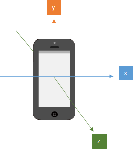
When the phone is stationary, the accelerometer still reports a value — roughly 9.8 m/s² along whichever axis is aligned with gravity. This is because gravity itself is a constant acceleration. The sensor cannot distinguish between gravitational acceleration and motion-induced acceleration, which is why the signal processing steps that follow are so important.
When you walk with a phone in your pocket, all three axes receive input simultaneously. Your body bobs up and down (Y-axis), sways slightly side to side (X-axis), and moves forward and backward with each stride (Z-axis). No single axis captures the full picture of walking — the motion is inherently three-dimensional.
B. Calculating the 3-Axis Vector Sum
Since walking motion is distributed across all three axes, we need a single composite value that reflects the overall magnitude of acceleration regardless of direction. This is the 3-axis vector sum (also called the Euclidean norm), calculated as:
Why not just use a single axis — say, the Y-axis for vertical motion? There are two reasons:
-
Phone orientation varies. The phone might be in a front pocket, a back pocket, held in your hand, or tucked into an armband. The axis that corresponds to “vertical” changes depending on orientation. The vector sum is orientation-independent.
-
Walking is multi-axis. Even with a fixed orientation, the characteristic “bounce” of walking produces acceleration on all three axes simultaneously. Using the vector sum captures the full energy of the motion, making detection more reliable.
This vector sum forms the basis for all subsequent filtering and threshold comparisons.
C. Noise Removal
The accelerometer is remarkably sensitive — it responds to even the slightest vibration. If we counted every acceleration spike as a step, the pedometer would be wildly inaccurate. Unwanted signals from phone handling, environmental vibrations, and sensor noise must be filtered out.
There are several approaches to noise removal. One common technique is the low-pass filter, which smooths the signal using the formula:
Y(t) = a * Y(t-1) + (1 - a) * x(t)Where Y is the filtered value, x is the raw data, t is the time index, and a is a smoothing constant between 0 and 1. Higher values of a produce more aggressive smoothing.
However, for this application, I chose a different approach: averaging every n samples and comparing against a threshold.
The method works as follows:
- Collect the last n accelerometer readings (where n is a configurable ring buffer size)
- Calculate the average of these readings for each axis
- Compute the vector sum of the averaged values
- If the vector sum exceeds a predefined threshold, count it as a step
The averaging over n samples acts as a natural smoothing function — random spikes get diluted by surrounding calm readings, while sustained rhythmic motion (walking) consistently produces averages above the threshold.
Why set the threshold high? This is a deliberate design decision. Since the goal is not just step counting but promoting effective exercise, the threshold is set high enough to require vigorous stepping — raising the thighs, swinging the arms. Gentle shuffling will not trigger the pedometer. This encourages the user to maintain the form recommended by exercise scientists for genuine aerobic benefit.
D. Delay Logic
There is one more consideration: the natural rhythm of walking. When you take a step, there is a minimum time interval before the next step can physically occur. A human simply cannot take two genuine steps within a few milliseconds of each other.
The delay logic enforces this constraint. After detecting a step, the system ignores all accelerometer input for a configurable duration (typically around one second). This prevents a single vigorous step from being counted multiple times due to the oscillating nature of the acceleration signal.
Without the delay, a single footfall could produce several acceleration peaks as the body decelerates, rebounds, and settles — each peak potentially exceeding the threshold and being falsely counted as a separate step.
The Code
Now let us look at the actual implementation. The pedometer consists of two main classes: SimplePedometerActivity (the Android Activity that manages sensors) and SimpleStepDetector (the algorithm that processes acceleration data).
SimplePedometerActivity.java
First, we obtain an instance of the accelerometer sensor and initialize the step detector:
@Override
protected void onCreate(Bundle savedInstanceState) {
  super.onCreate(savedInstanceState);
  textView = new TextView(this);
  textView.setTextSize(30);
  setContentView(textView);
  // Get an instance of the SensorManager
  sensorManager = (SensorManager) getSystemService(SENSOR_SERVICE);
  accel = sensorManager.getDefaultSensor(Sensor.TYPE_ACCELEROMETER);
  simpleStepDetector = new SimpleStepDetector();

}
simpleStepDetector.registerListener(this);
The Activity lifecycle methods manage sensor registration carefully. When the app goes to the background (onPause), we unregister the sensor listener to prevent unnecessary battery drain. When the app returns to the foreground (onResume), we re-register the listener and reset the step count.
The onSensorChanged callback fires every time the accelerometer reports new data. We pass the timestamp and three axis values directly to the step detector:
@Override
public void onPause() {
  super.onPause();
  sensorManager.unregisterListener(this);
}
@Override
public void onResume() {
  super.onResume();
  numSteps = 0;
  textView.setText(TEXT_NUM_STEPS + numSteps);
  sensorManager.registerListener(this, accel, SensorManager.SENSOR_DELAY_FASTEST);
}
@Override
public void onSensorChanged(SensorEvent event) {
  if (event.sensor.getType() == Sensor.TYPE_ACCELEROMETER) {
    simpleStepDetector.updateAccel(
        event.timestamp, event.values[0], event.values[1], event.values[2]);
  }
}
Note the use of SensorManager.SENSOR_DELAY_FASTEST — we request the highest possible sampling rate from the accelerometer to capture every nuance of the walking motion. The filtering and threshold logic in SimpleStepDetector will handle the volume of data.
SimpleStepDetector.java
This is the heart of the step detection algorithm. Let us walk through the updateAccel method:
public void updateAccel(long timeNs, float x, float y, float z) {
    float[] currentAccel = new float[3];
    currentAccel[0] = x;
    currentAccel[1] = y;
    currentAccel[2] = z;
    // First step is to update our guess of where the global z vector is.
    accelRingCounter++;
    accelRingX[accelRingCounter % ACCEL_RING_SIZE] = currentAccel[0];
    accelRingY[accelRingCounter % ACCEL_RING_SIZE] = currentAccel[1];
    accelRingZ[accelRingCounter % ACCEL_RING_SIZE] = currentAccel[2];
    // point A
    float[] worldZ = new float[3];
    worldZ[0] = SensorFilter.sum(accelRingX) / Math.min(accelRingCounter, ACCEL_RING_SIZE);
    worldZ[1] = SensorFilter.sum(accelRingY) / Math.min(accelRingCounter, ACCEL_RING_SIZE);
    worldZ[2] = SensorFilter.sum(accelRingZ) / Math.min(accelRingCounter, ACCEL_RING_SIZE);
    // point B
    float normalization_factor = SensorFilter.norm(worldZ);
    worldZ[0] = worldZ[0] / normalization_factor;
    worldZ[1] = worldZ[1] / normalization_factor;
    worldZ[2] = worldZ[2] / normalization_factor;
    float currentZ = SensorFilter.dot(worldZ, currentAccel) - normalization_factor;
    velRingCounter++;
    velRing[velRingCounter % VEL_RING_SIZE] = currentZ;
    float velocityEstimate = SensorFilter.sum(velRing);
    // point C
    if (velocityEstimate > STEP_THRESHOLD && oldVelocityEstimate <= STEP_THRESHOLD
            && (timeNs - lastStepTimeNs > STEP_DELAY_NS)) {
        listener.step(timeNs);
        lastStepTimeNs = timeNs;
    }
    oldVelocityEstimate = velocityEstimate;

}
Let me explain the three key sections:
Point A — Averaging for noise reduction. The raw acceleration values for each axis are stored in ring buffers of size ACCEL_RING_SIZE. The average of each axis buffer is computed, producing a smoothed estimate of the gravitational direction. This is not yet the vector sum — it is the per-axis average that will be used to separate gravity from walking-induced acceleration.
Point B — Vector sum and gravity compensation. The SensorFilter.norm() call computes the Euclidean norm (vector sum) of the averaged values, which represents the magnitude of gravity. By normalizing the averaged vector and computing the dot product with the current acceleration reading, then subtracting the gravity magnitude, we isolate the component of acceleration caused by walking motion — effectively removing gravity from the signal. The result is accumulated in another ring buffer (velRing) to produce a velocity estimate.
Point C — Threshold and delay check. The velocity estimate is compared against STEP_THRESHOLD. The condition requires that the estimate crosses the threshold from below (a rising edge), preventing multiple triggers from a single peak. The delay check (timeNs - lastStepTimeNs > STEP_DELAY_NS) ensures that consecutive steps are spaced by at least the minimum walking interval. STEP_THRESHOLD is intentionally set high to detect vigorous, exercise-level movement rather than casual fidgeting.
When a step is detected, the listener callback increments the step count:
@Override
public void step(long timeNs) {
    // count walking step
    numSteps++;

}
Summary and What Comes Next
At this point, we have a functioning pedometer that can reliably detect walking-in-place motion using the smartphone’s accelerometer. The implementation handles the key challenges of sensor-based step detection: multi-axis data fusion, noise filtering through sample averaging, threshold-based step recognition tuned for exercise-level movement, and delay logic that respects natural walking rhythm.
However, a pedometer alone only lets us move forward in a straight line. To create a true virtual sightseeing experience, we need the ability to turn left, right, and look around — which requires a completely different sensor: the gyroscope.
In the next part, we will implement gyroscope-based rotation detection, integrate both sensors with Google Street View, handle landscape screen orientation for TV casting, and see the complete system in action.
Virtual Sightseeing Series:
- Part 1: Walking at Home as Virtual Sightseeing — Concept and Step Detection (You are here)
- Part 2: Gyroscope Navigation, Street View Integration, and the Final Demo